Wastewater and water treatment runs in seven stages: screening, grit removal, primary sedimentation, biological treatment, secondary clarification, tertiary polishing, and disinfection. Each stage exists to protect the one behind it. Undersize an early stage and the consequence appears downstream, usually as a worn pump impeller, a foaming aeration basin, or a discharge sample that misses consent. Oil and grease deserve particular attention in that sequence, because free oil that reaches biological treatment stops being a separation problem and becomes an operating problem. This article walks the stages in order and shows where oil removal belongs.
What are the seven stages of wastewater and water treatment?
The seven stages move from coarse physical separation to fine chemical and biological polishing. Each one removes a narrower class of contaminant than the stage before it.
Screening removes rags, plastics, and large debris at the plant inlet.
Grit removal settles out sand, silt, and glass fragments before they reach pumps.
Primary sedimentation settles suspended solids and skims floating scum and oil.
Secondary biological treatment oxidises dissolved and colloidal organics.
Secondary clarification separates biomass from treated water and returns it to the process.
Tertiary polishing removes residual solids, nutrients, or specific contaminants.
Disinfection inactivates pathogens before discharge or reuse.
Stages 1 to 3 are physical. Stages 4 and 5 are biological. Stages 6 and 7 exist because secondary effluent alone rarely meets a modern consent. Sludge and scum removed along the way form a parallel stream with its own thickening, digestion, and dewatering train (see our guide to sludge handling and dewatering in industrial plants).
What happens during primary treatment?
Primary treatment covers stages 1 to 3 and removes material that gravity and a bar rack can handle without chemistry or biology. It protects every mechanical and biological asset that follows.
How do screens and grit chambers protect downstream equipment?
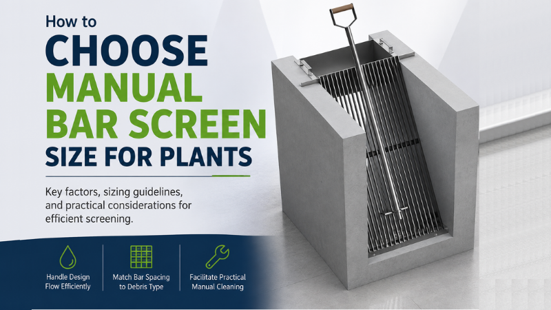
Screens intercept solids by physical size. Coarse screens catch rags, cloth, and bottles; fine screens catch fibres and small fragments that would otherwise wrap around impellers or blind membrane modules.
Coarse screen clear opening: 25–50 mm
Fine screen opening: 1.5–6 mm
Grit chambers work on density rather than size. The design target is a horizontal velocity low enough to settle inorganic grit of specific gravity around 2.65 while keeping lighter organic floc in suspension so it carries forward to the clarifier.
Grit chamber design velocity: 0.3 m/s (typical range 0.24–0.4 m/s)
Grit chamber detention time: 45–90 seconds
Grit that escapes this stage does not disappear. It abrades pump impellers, accumulates in aeration basin corners, and steadily eats the working volume of a digester.
What does primary sedimentation actually remove?
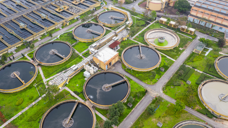
The primary clarifier gives suspended solids time to settle and floating material time to rise. Detention time is typically 1.5 to 2.5 hours in a tank sized ahead of biological treatment.
Primary sedimentation removal: 50–70% TSS, 25–40% BOD
The surface of that tank matters as much as the floor. Scrapers move settled sludge to the hopper while a surface skimmer pushes scum, grease, and free oil to a trough. In a municipal plant the primary clarifier is the principal mechanism for removing grease and oil, which is why plants built without primary clarification report more foaming trouble in the aeration basin.
How do secondary and tertiary treatment methods differ?
Secondary treatment uses microorganisms to consume dissolved and colloidal organic matter. Tertiary treatment is a physical or chemical polish applied after the biology has done what it can.
What happens in secondary biological treatment?
Activated sludge, trickling filters, MBBR, and MBR all cultivate a biomass that oxidises organics, then separate that biomass from the treated water. The separation step is the secondary clarifier, which returns most of the settled sludge to the process and wastes the remainder to sludge handling.
Under 40 CFR 133.102, the United States sets the baseline for secondary treatment:
BOD5: 30 mg/L (30-day average), 45 mg/L (7-day average)
TSS: 30 mg/L (30-day average), 45 mg/L (7-day average)
Minimum removal: 85% for both BOD5 and TSS
pH: 6.0 to 9.0
Process choice changes what is achievable. Trickling filters typically deliver 60 to 85% BOD reduction at a loading around 1 kg BOD/m³ per day, so a plant relying on a trickling filter alone has less margin against an 85% removal requirement than one running activated sludge. Sludge age, dissolved oxygen, and influent grease load together decide which organisms dominate the basin.
What does tertiary treatment add?
Tertiary treatment targets what biology leaves behind: residual suspended solids, nutrients, colour, specific organics, and pathogens. Media filtration, disc filters, membranes, activated carbon, and chemical dosing all sit here, followed by disinfection.
Disinfection performance is bound to the solids that reach it. Ontario’s design guidelines for sewage works suggest a UV dose of not less than 30 mW·s/cm² for an activated sludge effluent after allowing for lamp ageing and sleeve fouling, while the NWRI guidelines for water reuse set a design dose of at least 100 mJ/cm² at maximum day flow with filtered effluent transmittance of 55% or greater at 254 nm. Turbidity shields organisms from the lamps. So when a clarifier stops settling and effluent TSS climbs, the UV bank fails even though every lamp is lit. Adding lamp capacity to compensate for a clarifier that does not settle is the wrong fix.
In India, general standards under Schedule VI of the Environment (Protection) Rules, 1986 set the floor where no industry-specific standard applies:
Suspended solids: 100 mg/L (inland surface water), 600 mg/L (public sewers)
Oil and grease: 10 mg/L (inland surface water), 20 mg/L (public sewers and marine coastal areas)
pH: 5.5 to 9.0
Where does oil removal fit in a wastewater and water treatment plant?
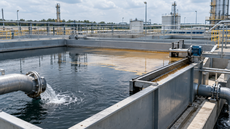
Oil removal is not a bolt-on stage. It belongs wherever the oil is still free and buoyant, which in practice means at or before primary sedimentation, and often in a dedicated separator upstream of the plant inlet.
Why must free oil be removed before biological treatment?
Three filaments known to cause activated sludge foaming, Nocardia, Microthrix parvicella, and type 1863, all grow on grease and oil. Foaming takes hold when high grease and oil load combines with a long sludge age and low dissolved oxygen or septicity. Once established, the foam is stabilised by physical interlocking of the filaments, so antifoam chemicals do little.
The operational cost lands in several places at once. Foam carries biomass over the clarifier weir and raises effluent TSS. Nocardia cells float whether alive or dead, so the problem follows waste activated sludge into the digester. And a foam blanket spilling out of an aeration basin is a slip and access hazard for operators working around the walkways.
Which separation method matches which droplet size?
Gravity separation is governed by the rise velocity of an oil droplet, which depends on the density difference between oil and water, water temperature, and viscosity. Droplet size sets the practical cut point for each technology.
API 421 separator: droplets down to approximately 150 microns
Corrugated plate interceptor: droplets down to approximately 60 microns
Typical API separator effluent: 50–200 mg/L
Separators designed to API Publication 421 rely on maintaining laminar flow, and the standard limits horizontal velocity to keep it laminar. Plate packs achieve a finer cut in a smaller footprint because the plates shorten the distance a droplet must rise before it coalesces on a surface. Below roughly 60 microns, and for oil held in a chemical or mechanical emulsion, gravity alone will not do the job and the duty passes to dissolved air flotation with emulsion breaking, or to filtration (see our guide to selecting an oil–water separator for oily effluent).
Two specification errors recur. The first is sizing a separator on flow alone, without the oil’s specific gravity or the effluent temperature, both of which move the rise velocity directly. The second is ignoring solids. Plate packs foul when solids loading is high, which is why common design practice widens plate spacing to around 20 mm and steepens the plate angle to 60 degrees when feed TSS exceeds roughly 500 mg/L, rather than the 45 degrees used for clean feeds.
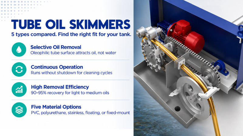
Recovering the separated layer is a separate duty from separating it. Oleophilic skimmers in tube, belt, drum, and disc formats pull the floating oil off continuously so the layer never thickens enough to carry under a baffle or reach the outlet weir during a flow surge. Continuous removal also returns a lower-water-content oil for recovery (see our guide to oil skimmer types and where each one suits).
Conclusion
Effective wastewater and water treatment depends on seven stages working in sequence, each sized for the load the previous stage actually passes on. Screens and grit chambers protect mechanical assets. Primary sedimentation removes 50 to 70% of TSS and doubles as the plant’s main defence against grease reaching the aeration basin. Secondary treatment carries the organic load against benchmarks such as the 85% BOD5 and TSS removal set out in 40 CFR 133.102, and tertiary polishing plus disinfection closes the gap to consent. Oil and grease removal belongs early, matched to droplet size, because free oil left in the flow becomes a foaming and compliance problem that no downstream stage can economically undo.
FAQs
Q1. What are the seven stages of wastewater and water treatment?
A: The seven stages are screening, grit removal, primary sedimentation, secondary biological treatment, secondary clarification, tertiary polishing, and disinfection. Each stage removes a finer class of contaminant than the one before it, so early stages protect the capacity and reliability of later ones.
Q2. How much BOD and TSS does primary sedimentation remove?
A: A primary clarifier typically removes 50 to 70% of total suspended solids and 25 to 40% of BOD, at a detention time of roughly 1.5 to 2.5 hours. The remaining organic load passes forward to biological treatment.
Q3. What is the difference between secondary and tertiary treatment?
A: Secondary treatment is biological. Microorganisms oxidise dissolved and colloidal organics, and a clarifier separates the biomass. Tertiary treatment is a physical or chemical polish applied afterwards, covering filtration, nutrient removal, adsorption, and disinfection before discharge or reuse.
Q4. Why does oil and grease need removing before biological treatment?
A: Filamentous organisms including Nocardia and Microthrix parvicella grow on grease and oil, and produce a stable foam when high oil load combines with long sludge age and low dissolved oxygen. The foam carries solids over clarifier weirs, follows sludge into digesters, and resists antifoam chemicals.
Q5. What size oil droplets can an oil–water separator remove?
A: A gravity separator designed to API Publication 421 removes free oil droplets down to approximately 150 microns. A corrugated plate interceptor reaches around 60 microns in a smaller footprint. Emulsified oil below that range requires dissolved air flotation with emulsion breaking, or filtration.
Q6. What are the discharge limits for oil and grease in India?
A: Under Schedule VI of the Environment (Protection) Rules, 1986, general standards set oil and grease at a maximum of 10 mg/L for discharge to inland surface water and land for irrigation, and 20 mg/L for public sewers and marine coastal areas. Industry-specific standards override these where they exist.