How to choose oil water separators for power plants comes down to one thing: matching the separator design to the plant’s hydraulic load, oil-droplet behavior, and performance target. A good system is built around API Publication 421, EN 858 Class I performance philosophy, and Stokes Law, with verification against a low outlet Oil & Grease target of ≤ 5 mg/L.
Oil water separators for power plants are not just passive tanks. They are engineered treatment systems that use flow conditioning, primary gravity separation, CPI technology, secondary coalescing media, oil collection, and sludge management to maintain stable performance under real operating conditions. The best choice is the one that keeps all of those stages working together.
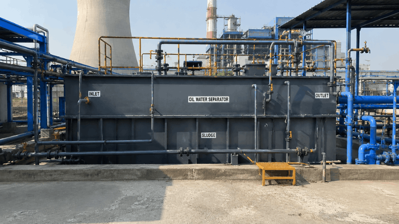
What are oil water separators for power plants?
A separator for a power plant has to separate free oil, dispersed oil, and settleable solids while keeping hydraulic behavior stable.
How does the separator actually work?
Oil droplets rise because oil is lighter than water, while heavier solids settle downward. The separation rate depends on oil droplet size, fluid properties, density difference, residence time, and flow stability, which is why hydraulic design matters so much.
A power plant separator usually works in stages. Inlet flow conditioning slows and stabilizes the incoming stream, primary gravity separation removes larger droplets, CPI increases effective surface area, and secondary coalescing media polishes the effluent before discharge.
Why does a multi-stage design matter?
A single separation mechanism rarely gives reliable low-oil performance across all operating conditions. The performance guarantee comes from the combined effect of gravity separation, enhanced surface area, oil droplet coalescence, controlled hydraulics, oil recovery, and sludge management.
That means a separator should be judged as a complete system, not as one chamber with a nameplate rating. If one stage is weak, the whole train becomes weaker. No drama, just physics.
What are the key performance specifications to evaluate?
The important question is not “Does the unit exist?” The real question is “Will this separator hold performance at design flow and still meet the outlet target?”
Which performance values should be checked first?
Start with the parameters that directly affect separation quality and stability:
Design flow rate — The separator should handle the required m³/hr without unstable operation.
Outlet Oil & Grease target — The design basis in the uploaded document is ≤ 5 mg/L.
Hydraulic stability — The unit should avoid short-circuiting, turbulence, or flow upset.
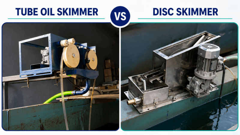
Oil recovery continuity — Separated oil should be removed continuously to prevent re-entrainment.
Sludge handling capacity — Sludge storage zones should protect active separation areas from accumulation.
Those are the deal-breakers. If a separator looks good on paper but cannot maintain these conditions, the performance guarantee becomes wishful thinking dressed up as engineering.
Why do API 421 and Stokes Law matter in specification review?
API Publication 421 provides the hydraulic design principles for oil-water separators. The standard covers oil droplet separation by gravity, separator sizing philosophy, surface loading, hydraulic residence time, oil rise velocity, and stable flow distribution.
Stokes Law explains why droplet size matters so much. Smaller droplets rise more slowly, which means the separator needs the right residence time and flow control to achieve separation before the treated water outlet.
What does EN 858 Class I imply for selection?
EN 858 Class I performance philosophy is used for separators intended to achieve outlet oil concentrations below 5 mg/L under specified operating conditions. It also supports enhanced separation devices such as coalescing systems when low residual oil concentration is required.
That makes EN 858 useful as a performance benchmark. In simple terms, the separator should not just separate oil; it should reliably polish the wastewater to a very low residual oil level under the actual plant duty.
How should oil water separators for power plants be sized?
The right separator size is not the one that looks biggest. It is the one that gives stable separation at the plant’s design flow while preserving enough residence time and surface area for oil rise and capture.
What data should be used for sizing?
Sizing should be based on the wastewater characteristics that actually reach the separator. The design basis should consider wastewater within design limits, free and dispersed oil, stable flow conditions, and the absence of stable emulsions.
A practical sizing review should include:
Design flow rate in m³/hr
Expected inlet Oil & Grease concentration
Oil droplet behavior and separation difficulty
Residence time needed for gravity separation
Space available for gravity chamber, CPI, and coalescer sections
If those inputs are vague, the sizing will be vague too. And vague sizing is how projects end up with expensive equipment that is “technically installed” but operationally underwhelming.
Why is flow conditioning part of sizing?
Flow conditioning is not a bonus feature. It is what keeps the separator calm enough for gravity separation to work properly. The controlled hydraulic conditions are part of the performance guarantee, and that includes stable flow distribution through the separator stages.
Without proper flow conditioning, turbulence can break up droplets, disturb settled solids, and reduce oil recovery. So a separator should be sized as a hydraulic system, not as a storage box.
Why does CPI technology affect footprint and capacity?
The Corrugated Plate Interceptor increases the effective separation surface area inside a compact footprint. It also reduces droplet travel distance and improves the chance of coalescence, which helps separate smaller droplets that gravity alone may not remove efficiently.
That matters in power plants where layout space is often limited. A CPI stage can make the design more compact without sacrificing separation performance, provided the upstream flow and sludge handling remain controlled.
Which compliance standards and maintenance requirements matter most?
A separator that meets design intent on day one but drifts out of spec later is not a good separator. It is just a short-lived success story.
What standards should guide the final selection?
The uploaded document identifies three core technical references:
API Publication 421 for hydraulic design principles
EN 858 Class I for low-residual-oil performance philosophy
Stokes Law for the separation physics of oil droplets in water
Those standards form the design basis. In addition, the separator should be verified against commissioning tests and acceptance criteria that confirm design flow, stable operation, and outlet Oil & Grease ≤ 5 mg/L.
What maintenance requirements should be checked before selection?
Maintenance is part of design, not a separate afterthought. The routine maintenance, periodic oil removal, and periodic sludge removal are part of the performance assumptions. It also notes that CPI and coalescing media must remain serviceable for the separator to meet its guarantee.
A practical maintenance review should confirm:
Oil collection is easy to access
Sludge chambers can be cleaned
Instruments can be calibrated
Sampling points are accessible
CPI and coalescing media can be inspected or replaced
If maintenance is complicated, performance usually decays faster. Simple enough, annoyingly enough.
Why do FAT and SAT matter in procurement?
The FAT and SAT observations are part of the design validation and performance confirmation basis. The verification matrix compares actual measured values against guaranteed values for flow rate, inlet Oil & Grease, outlet Oil & Grease, hydraulic stability, oil recovery, and sludge management.
That means procurement should not stop at drawings and datasheets. The separator should be tested and accepted against measurable performance criteria, not just promised performance.
How do you compare separator options in a real project?
When teams evaluate oil water separators for power plants, the winning unit is usually the one that balances hydraulic design, compact footprint, and serviceability without sacrificing the outlet target.
What should the comparison matrix include?
A clean comparison matrix should ask:
Does the design follow API 421 hydraulic principles?
Does the unit support EN 858 Class I-style low residual oil performance?
Does the system use CPI and secondary coalescing where needed?
Does the design support continuous oil recovery and sludge management?
Can the separator be verified through FAT and SAT against the guarantee?
This approach keeps the discussion technical and useful. It also helps avoid the classic procurement trap where a lower-price option quietly loses the performance battle later.
What signs suggest a stronger separator design?
A stronger separator design usually shows the following traits:
Stable hydraulic layout
Multi-stage separation path
Continuous oil collection
Dedicated sludge zones
Clear commissioning verification method
Those features point to a system that is built to work in the field, not just in a catalog.
Conclusion
Choosing oil water separators for power plants is about aligning design, physics, and operating discipline. The strongest selection is one built on API Publication 421 hydraulic principles, guided by EN 858 Class I performance philosophy, and grounded in Stokes Law. The separator should be sized for real flow, not average flow, and it should use flow conditioning, primary gravity separation, CPI, and secondary coalescing as a linked system. The final check is commissioning: design flow achieved, stable hydraulic behavior, continuous oil recovery, functional sludge management, and outlet Oil & Grease concentration of ≤ 5 mg/L.
Frequently Asked Questions (FAQs)
Q1. What is the most important factor when choosing an oil water separator for a power plant?
A: The most important factor is whether the separator can meet the design flow while maintaining stable separation and an outlet Oil & Grease concentration of ≤ 5 mg/L. A separator that cannot hold hydraulic stability or oil recovery under real plant conditions will not perform reliably.
Q2. Why is CPI technology useful in oil water separators?
A: CPI technology increases the effective separation surface area and shortens the droplet travel distance. That improves the chance of coalescence and helps the separator remove smaller oil droplets more effectively than gravity separation alone.
Q3. What does EN 858 Class I mean in practice?
A: EN 858 Class I is a performance philosophy for oil separator systems intended to achieve outlet oil concentrations below 5 mg/L under specified conditions. In practice, it means the separator should deliver low residual oil performance, usually with enhanced separation devices like coalescing media.
Q4. Why are FAT and SAT important for separator selection?
A: FAT and SAT matter because they verify actual performance against guaranteed values. The performance framework checks flow rate, inlet and outlet Oil & Grease, hydraulic stability, oil recovery, and sludge management before acceptance is confirmed.